FM0 I/O CIRCUIT AND WIRING DIAGRAMS FM2 Wiring diagram Color code of connector attached cable (Brown) V 1 (Black) CH1 D2 (Comparative output 1) Load Main circuit Tr2 1 kΩ approx Varistor (Note 1) Internal circuit Load Load 50 mA max (White) CH2 (Comparative output 2 / External input) 50 mA max 4 (Gray) Analog voltage output (Note 2) 5
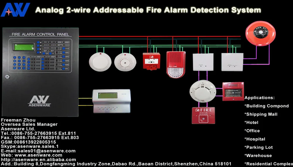
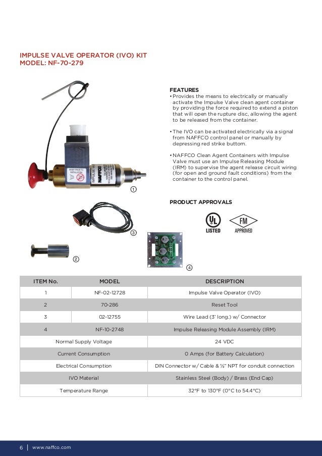
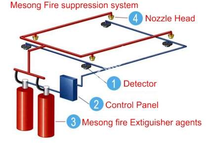
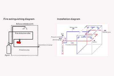
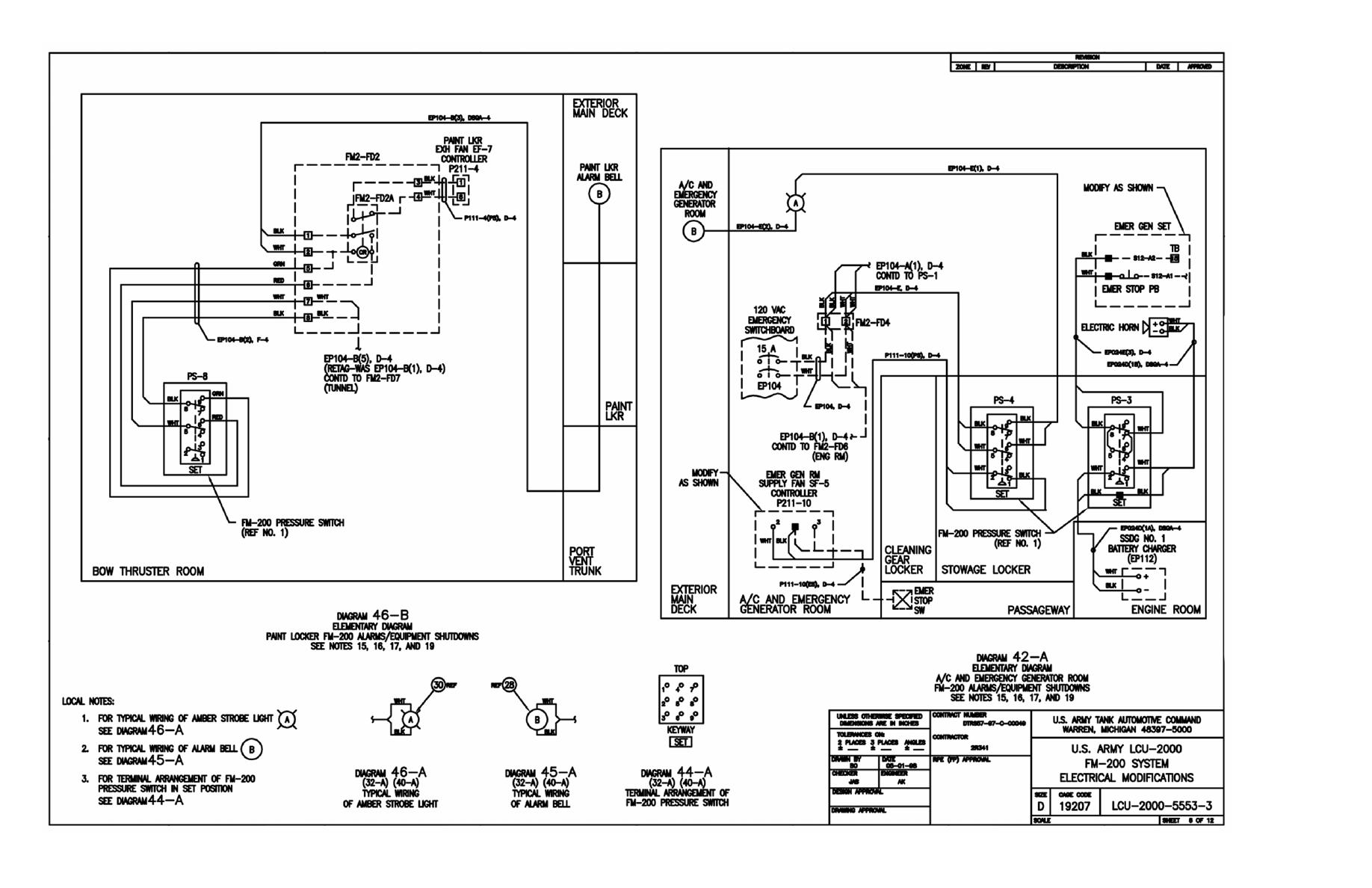
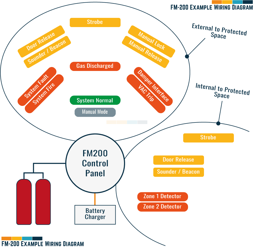
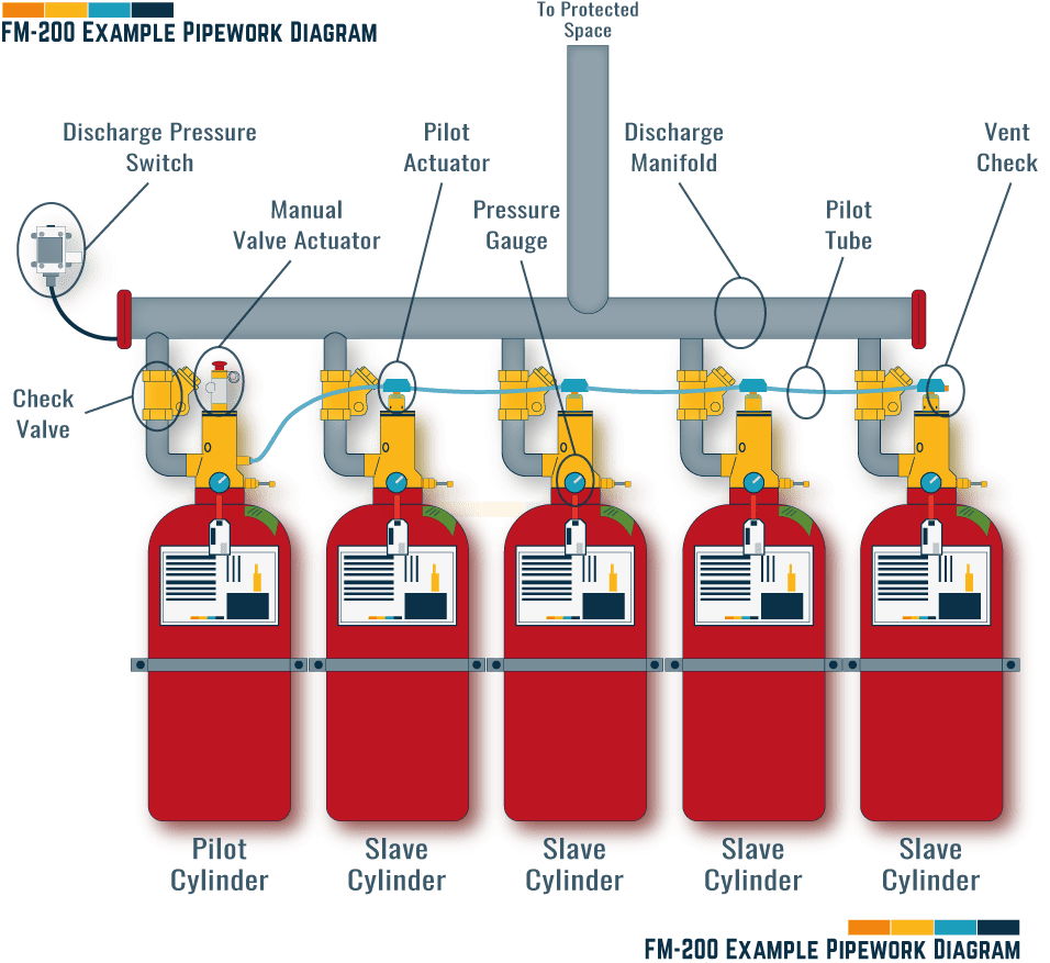
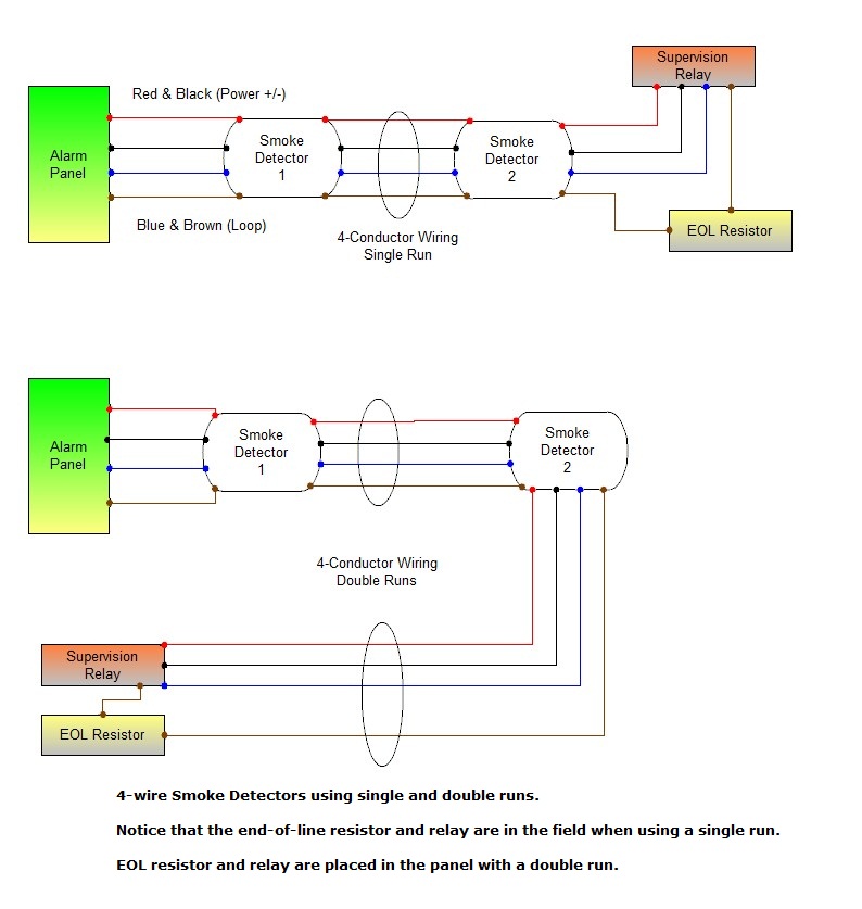
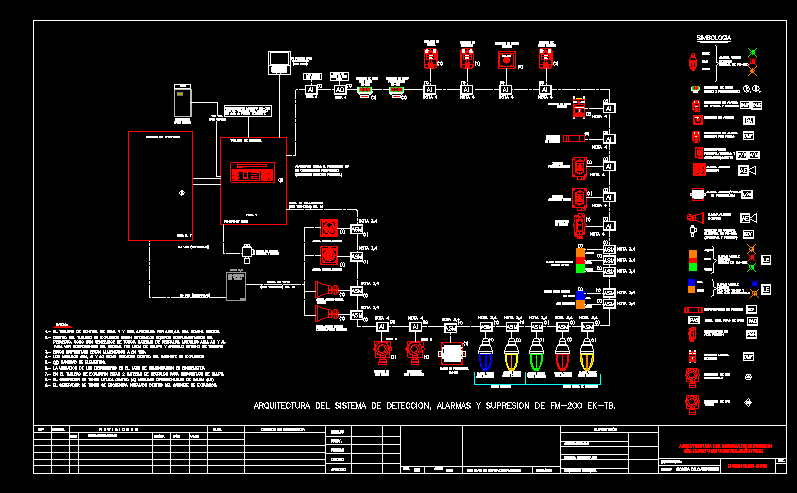
Fm 200 system wiring diagram-Compartment, always install safety pin extinguisher system to avoid accidental discharge at completion of maintenance, remove safety pin from trigger assembly, and store in holding tie located on cylinder owner's manual & installation guide seafire fm0 ® automatic fire extinguisher manual part no 3 Agent FM0 Fire Suppression System to be located in the new Data Center on the 5th Floor of the WTCB The TO Contractor is to provide all labor, tools, equipment, hardware and consumables to furnish and to install a fully integrated and functional FM0 Fire Suppression System The Department expects a "turnkey" solution for this project
Fm 200 system wiring diagramのギャラリー
各画像をクリックすると、ダウンロードまたは拡大表示できます
 |  |  |
 |  | |
 |  | |
 |  |  |
「Fm 200 system wiring diagram」の画像ギャラリー、詳細は各画像をクリックしてください。
 | ||
 |  | |
 | ||
「Fm 200 system wiring diagram」の画像ギャラリー、詳細は各画像をクリックしてください。
 |  | |
 |  | |
 | ||
 |  |  |
「Fm 200 system wiring diagram」の画像ギャラリー、詳細は各画像をクリックしてください。
 |  | |
 |  |  |
 | ||
 |  |  |
「Fm 200 system wiring diagram」の画像ギャラリー、詳細は各画像をクリックしてください。
 |  |  |
 | ||
 | ||
 |  | |
「Fm 200 system wiring diagram」の画像ギャラリー、詳細は各画像をクリックしてください。
 |  | |
 |  |  |
 | ||
 | ||
「Fm 200 system wiring diagram」の画像ギャラリー、詳細は各画像をクリックしてください。
 |  | |
 | ||
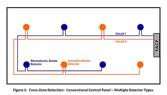 |  | |
 |  | |
「Fm 200 system wiring diagram」の画像ギャラリー、詳細は各画像をクリックしてください。
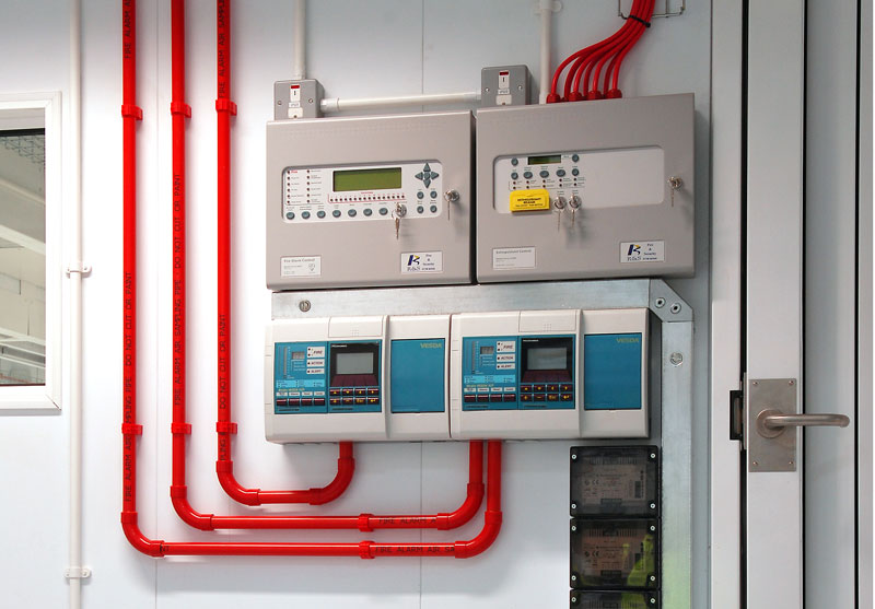 |  |  |
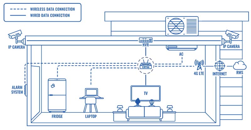 |  | 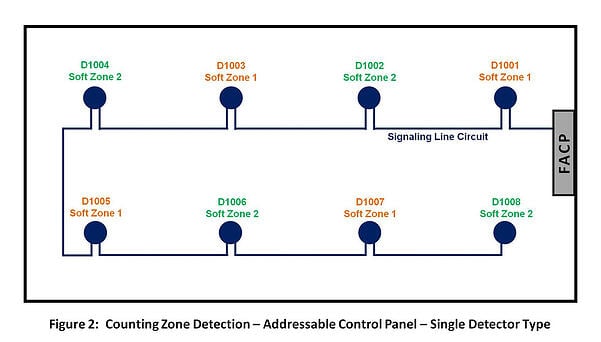 |
 |  | |
 |  | |
「Fm 200 system wiring diagram」の画像ギャラリー、詳細は各画像をクリックしてください。
 |  | |
 |  | |
 |
The ANSUL FM0 Clean Agent Fire Suppression System is approved by Factory Mutual (FM) and listed by Underwriters Laboratories (UL) for Class A, B and C fires Safe for use in occupied areas at the design concentration, the system helps protect critical infrastructure and delivers effective asset protection The system uses FM0 (HFC227ea The FM 0 supplier's authorized agent normally recommends 7% as the design concentration, based on their experience with the type of fire anticipated in the areas protected Increase of the agent concentration from 7% to 744% has the repercussion on the cost of the agent If possible, the recommendation of the AHJ (Authority of Jurisdiction
Incoming Term: fm 200 system wiring diagram,


0 件のコメント:
コメントを投稿